Friday, 25 November 2011

Exponentially Challenged

Despite my best efforts, I can't seem to get a working exponential converter hooked up. The majority of the designs I can find online use OTAs and have an output current rather than a voltage, so are useless. The one useable design I have found is this one on the EA site, but I can't seem to get it working. I'm using a TL084 quad op amp  for it rather than having an OP-7 for the final stage, so maybe that's the problem, though it does look like any standard kind of op amp should fit in there!


I'm considering a full redesign of the VCO now using OTAs. Saw a triangle/square VCO schematic in the LM13700 Datasheet that looks promising:


If I can make that work then I can keep my existing triangle-to-sine circuitry and find a new exponential converter design. Then I can design the PCB, get two of the damn things onto a board and be done with the VCO section! THEN I can finish my sequencer!

Wednesday, 23 November 2011

Hmmm...

Thinking about it a bit more, I should probably finish the VCO first, as really I want to use 12 position rotary switches hooked up to resistor ladders for the steps on the sequencer, and I won't know what values of resistors to use or be able to test and fine tune it until I have the VCO built with a proper 1v/oct input.

Also here's a test vid of the original 4 stepper:


Gutted I didn't think to record a vid when I switched in a smaller capacitor and went into hyperspeed!

Sequence me uppah!

Right, so the VCO is finished design-wise; I've got the thing laid out half on stripboard half on breadboard and the schematic is done in Eagle. Now I just have to design the PCB and I'm off and away!

In the meantime I've decided to expand my little sequencer. As I said in the last post I breadboarded a little 4 stepper to play with. Here's the whole setup as it was looking:


So I've now done a stripboard layout based on the Same schematic, added some resistors for the LEDs and an 8 position rotary switch to select the number of steps by connecting the reset pin to one of the the outputs, which gives me this:


Apologies for the sideways-ness. As you can see I've left plenty of room on the board, as I'm planning to add another chip and upgrade to 16 steps.

I was a bit short on potentiometers so I just wired up the first four as a tester, and the whole thing seemed to be working perfectly, apart from the fact that I couldn't make a four step sequence! 3 steps worked fine, and when i turned the switch to 5 that worked fine, but for some reason 4 gave me the whole ten steps! not even eight! the full TEN!  I triple checked all the connections and decided maybe I'd static damaged the 4017 chip, so I swapped it out for another one but must have had a wire touching the underside of the board or something because then something went bang. After much chin scratching and another 4017 replacement I realised it had been the 555! swapped that out and the whole thing is working fine now. Just need to buy a few more potentiometers and find a box to put it in and we're rockin'!

It may seem like I've neglected the VCO a bit to work on this, but it doesn't matter how nice my sine wave is if I don't have any way to make music with it. having this sequencer set up will help me get more of an idea of how stuff will sound as I progress through the rest of the project.

Also, I just realised that by giving it an external clock input hooked to an audio output from my computer I can send a pulse to it on every beat (or 1/2, or 1/4, etc) so that the sequencer will be in time with a midi track.

HOW BLOODY COOL IS THAT!

Monday, 21 November 2011

Skip a few...99. 100!

Right, While I've not been updating this thing I have actually advanced the project quite a bit, to the point that it's not worth me trying to fill in the gap in any kind of detailed way. The following is a brief summary of what's happened since the schmitt triggers:

I made an ADSR generator, didn't work. Then I thought maybe it was because I had to have a VCA to connected the ADSR and the oscillator into. Did this,  still didn't work. Scrapped the ADSR, focused onthe oscillator. Built a triangle generator, decided to then build a sine oscillator and realised how much harder a nice roundy wave is to make! looked at lots of different sine wave generation techniques, read this!
Looked around for schematics, tried to build Thomas Henry's VCO-1 but it wouldn't work. Copied just the triangle to sine section of his design and used it with this triangle generator to nice effect; then realised that the resulting circuit wasn't voltage controllable. Couldn't get Thomas Henry's version working for some reason, in fact any circuit I tried that used OTAs (Operational Transconductance Amplifiers, they produce a current instead of a voltage and have a 'bias input' which affects the current at the output) wouldn't work! Set about looking for a voltage controlled triangle wave generator circuit that just used standard op amps and found this bad boy. Built it, hooked it up to the breadboard triangle to sine converter and felt very pleased with myself.

I've also built a 4 step sequencer, also on breadboard and based on the 'Baby 10' sequencer.

Now I have to build an exponential converter for the VCO and put the whole thing on a PCB, so I'm working on the schematic and looking at PCB etching techniques. More details on this present situation in the next post.

Phew! Glad that's over, Now I can actually start updating this regularly with the stuff I want to talk about!

-JW

Tuesday, 8 November 2011

Fun with Schmitt triggers!

Been browsing the schematics on Experimentalists Anonymous again (I'll just refer to it as EA from now on for speed of typing!) and found an ADSR Generator I think I can tackle. I got some CD4093 Quad Schmitt Triggers today and have decided to give it  go and see if I can't hook it up to the square wave oscillator for some impressive sounding results.

In the meantime I found this site which describes an interesting little oscillator circuit that can be made with the 4093 chips. Obviously the end result is no good for my final project, but I'm learning here! lots of fun to play with anyway, crazy sounds galore! I suggest you have a go at building these circuits as it's good practice for putting things together on breadboard. The approach I took was to wire up the circuits based on the schematic and then if it didn't work check the breadboard picture to see where I went wrong. Usually I'd forgotten to wire up the power and/or ground connections to the chip, very frustrating!

I practiced putting the circuit together and taking it apart again until I could do it without looking at the site. I'm still not entirely sure how the chips actually makes the oscillations, but I'm trying to learn as much as I can here and I think a good approach is to try to learn the layouts of all the chips I'm using and how they behave when connected in various ways. I highly recommend printing out the datasheets/pinout diagrams for any chips you're using in your circuits and having them pinned up nearby for easy reference, as it saves a lot of time clicking about to get them up on-screen.


Now to tackle the ADSR generator...

Monday, 7 November 2011

Getting Practical

After building the square wave oscillator shown in the last post I found I couldn't get it to work. Turns out I have completely misunderstood some basic principles of schematics. I had assumed that points marked V+ went to the power supply (in my case a 9v wall wart type affair) and V- went to ground. Turns out that I was wrong, and there is such a thing as a negative voltage! After a bit of research I think I kind of understand it. Basically imagine you have two 12v batteries. if you wire them up in series you have a 24v supply, with 0v (what I would previously have used as ground) at the negative terminal of the first battery and +24v at the positive terminal of the second battery. But if you make ground the point between the two batteries, then instead of having +24V at one end and 0v at the other you suddenly have +12v and -12V.

This is still a problem for me as I only have this poxy 9v supply, and since my multimeter arrived in the post I've found out that it's actually outputting more like 15v!! Not to fear, I have a brilliant idea...

There's an old PC in my wardrobe that hasn't been in use for some time. Checking online I've found that ATX power supplies have cables to supply +12v, -12v, +5v and ground connections, so it could make the ideal poor mans hobby supply for my project!


Here is the pinout for the standard ATX connector:


My Supply had two sets of Molex connectors coming from it, so I cut one set off and used it to extend the other set to reach the top of my desk. I then ran a cable from pin 14 of the ATX connector as well. In order to make the supply switch on I had to put a jumper between pin 16 and 17. I used a piece of metal from inside a discarded Molex connector but any bit of wire you have lying around should do the trick.


Here I was glad I'd sprung for the nice breadboard with the screw terminals at the top, as I could connect all the cables there nicely, with colour coded screw on bits! the green terminal in the pic is connected to the audio in of my computer so that I can get a good listen to whatever oscillations I produce.


With this setup firmly entrenched on my desk I set about trying various circuits out, starting with the Square Wave Oscillator I mentioned last time. As I mentioned in my first posts, I'm typing all this retrospectively, So I don't have the circuit set up to take pictures anymore, but I built versions of it with the TL084 op amps and with the UTC4558s I found in the karaoke machine and both worked well. 

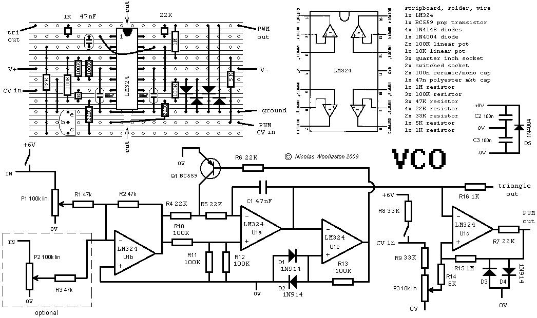
So! That's the square wave covered, now I just need Triangle, Sawtooth and Sine, and I'll have a VCO...ish. I wonder how you implement CV inputs?

Oscillator deflater

With the function generator not being much use, It's clear that the starting point for this beast has to be the VCO (Voltage Controlled Oscillator). A quick look online for some VCO schematics throws up circuits like this:

Which is all fine and dandy, but possibly a little complex as a starting point given that my electronics experience up to this point includes making an LED flash on and off in a year 9 physics class and soldering a resistor into an Xbox DVD drive to flash the firmware.

I'd best start with something simpler then.

Found this site on my travels: Experimentalists Anonymous. Lots of interesting stuff in their archives, looks like a synth schematics gold mine! Looking through the various articles I keep coming across a schematic symbol that I don't recognise, it's this little chap:
The operational amplifier (Op-Amp) seems to play a key role in most parts of an analog synth, especially the VCO and VCA modules. Looking for more information I found a few resources aimed at relative beginners. A bit of Googling around found me this page which shows a basic square wave oscillator using one op amp. the chip used in this example is a UA741, but any standard sort of op amp should work. I ordered a bunch of TL084 quad op amps for my toying around, as I'd seen these used in some of the more serious VCO circuits I'd looked though on Experimentalists Anonymous. I also found a bunch of UTC4558 op amps in a karaoke machine which I took apart, which seem to do the job just fine as well!

And so it begins...

Okay, right, making a synth! Easy!

Erm...

Okay I'll be honest, I've already made a bit of a start on the whole thing before I thought to make this blog, so these first few posts are sort of catcher-uppers for you. I'll try to fill you in as much as possible on the story so far, which started with a trip to my local Maplin...

I went there to buy some basic electronics supplies (Breadboard and GCSE Component Pack) and I noticed they had a "function generator kit" for sale which claimed to produce Saw, sine, triangle and square waves of varying frequencies. This seemed like a good way to get my feet wet before embarking on the project proper, So I bought it up and took it home.


I should point out here that I don't havea decent digital camera working at the moment so until that's sorted I can't take any pictures to put on here, but the kit looks like this:
I whipped out my trusty battery powered soldering iron and proceeded to put it together, realizing in the proccess that I would need a new soldering iron, as 3watts just isn't enough power for any kind of serious work!
After sifting through my various boxes of junk I found an old 9v power supply to power it, and found that it did indeed output several different waves at varying frequencies, but they all sounded a bit...square. Maybe it was too much to ask tto get all that functionality for £11.99!